

When a typical two-conductor footswitch (latching or momentary) is inserted into the appropriate jack on a device like a drum machine, rack delay, synthesizer, etc. and the footswitch is engaged, the device is expecting to see something that was previously disconnected become connected, or vice versa. When you engage the switch, you're physically changing something in that part of the circuit to either being connected (closed) or not-connected (open).
In modular synth terms, it might be tempting to think of a signal that goes from +5V to 0V to be like saying "Turn off". And while 0V might indeed be related to the device's internal ground reference (or more accurately, "common reference"), it isn't the same thing as physically shorting a connection to ground. So your drum machine might not be responding to your modular synth as you'd expect because it's looking for one thing and you're giving it another.
The trick then is to differentiate between two voltages that we designate as "on" and "off" and convert one of those electronic states into the physical state of being grounded. This can be accomplished with an electronic switch, provided it includes a common jack that connects to one or the other of a pair of I/O jacks. I haven't seen many of these around in the modular synth world, but the Q128 Switch from synthesizers.com is an example of one.
(If you know of others, tell me about them, and I'll list them here.)
Taking the foot out of switch
The Q128 Switch's jack labeled "A" is connected to the COMMON jack when the CONTROL signal is high, and the jack labeled "B" is connected to COMMON when CONTROL is low. Only A or B is connected to COMMON at a time. This is true when using the Switch to send a single signal to one of two destinations, or to send either of two signals to a single destination.
If a shorting plug -- a simple device that even someone with the most modest of soldering skills can make (see more on this below) -- is inserted into the switch's COMMON jack, then that jack is shorted, as is anything else connected to it (i.e. whichever of A or B is selected by the CONTROL jack's high/low state). Thus it's possible to short a jack (i.e. make it "open") using a control signal, just like pressing a footswitch.
But what are we actually shorting these jacks to? Earlier I used the phrase "shorting a connection to ground". In this context, "ground" means a common reference point that may or may not be actual earth ground. Regardless, it's a black hole from which no signal returns.
Often you don't need to think about this: Two electronic devices sitting in front of you each have an internally established ground reference which is very likely derived from the same place if both devices are plugged into the same electrical outlet (or even different outlets on the same circuit). When you connect the devices together with a patch cable, each plug's metal sleeve touches a corresponding spot (also called sleeve) inside the jack, which is itself connected to that device's internal ground reference. As long as both devices (ahem) "establish common ground", things generally work as expected.
Enough theory though. Why does shorting a jack to ground, whence no signal returns, cause something desirable to happen?
Consider the Roland CR-78 CompuRhythm (photo of its backside below). A tap on a momentary footswitch plugged into the drum machine's START/STOP jack starts the CR-78, and another tap stops it. That's because a tap on the switch briefly shorts the jack to "ground" (or what the CR-78 calls ground). Inside the CR-78, the sleeve portion of its START/STOP jack is connected to its internal ground reference. Inside the footswitch, the plug's tip is either connected or not connected to its sleeve, depending on whether the pedal is being depressed or not. Though not powered itself, when it's plugged into the CR-78, the footswitch becomes part of an active circuit.
Let's say the polarity of the footswitch is such that pressing the pedal connects the plug's tip to its sleeve. That means the tip portion of the START/STOP jack into which the plug is inserted is now also connected to its sleeve (i.e. ground). Another way you might hear this stated is that pressing the footswitch "pulls the CR-78's START/STOP jack to ground". This is a different state than before the footswitch was pressed. Some part of the CR-78's circuit is watching for that state change, and starts or stops the machine accordingly. The VARIATION and WRITE jacks work the same way.

Using an electronic switch like the Q128 mentioned above, the same thing can be accomplished with a control voltage by:
- Connecting the Q128's A jack to the CR-78's START/STOP jack
- Inserting a shorting plug into the Q128's COMMON jack
- Sending a CV pulse to the Q128's CONTROL jack
With this configuration, the shorting plug connects the COMMON jack's tip to its own sleeve, which is referenced to ground within the Q128's own circuitry. Thus whichever of jacks A or B is active, that jack will be pulled to ground.
The CONTROL jack's "normal" state (no pulse) is low, which means A is not connected to COMMON (the B jack is; but what's more important is that A is not). Sending a pulse from the modular or DAW to the CONTROL jack causes it to go high for the duration of the pulse, momentarily connecting the A jack to ground. The CR-78 sees that state change, and it starts playing (or stops, if it was already playing).
This trick should work to give you CV control of all kinds of unique functions on gear with footswitch jacks. Give it a try and let me know how it goes for you!

If you're curious and want to see this on an oscilloscope, monitor some external signal (e.g. +1V DC), and then connect the Q128's A jack to the same scope channel. You'll see the positive DC pulled to 0V each time the Q128's CONTROL signal goes high.
Side note: Reinserting cables can leave the CR-78 in a stuck state. If it stops responding, usually pressing the START/STOP button once will clear it up. If not, reinsert the Q128 CONTROL cable. If you're sending CVs from your DAW, sometimes this needs to be done while the DAW's transport is running. So far I've only encountered this quirky behavior with the CR-78.
DIY shorting plug
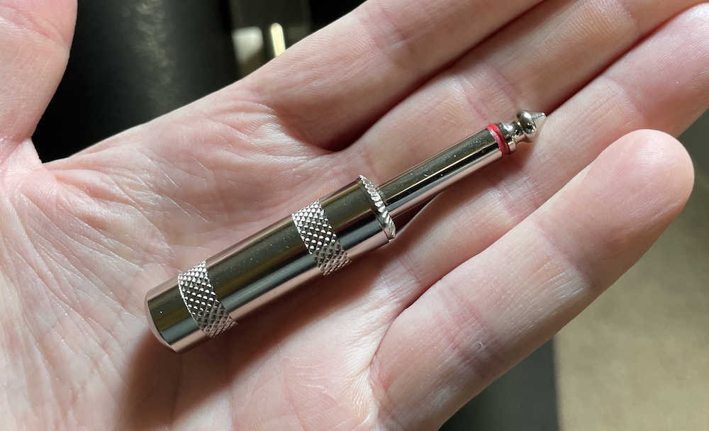
It's exceedingly easy to make one. Grab a 1/4" mono (2-conductor / Tip-Sleeve) plug -- the same type used for your modular patch cables. I like to use the Switchcraft 280, but there are others, like the Neutrik NYS225. The same concept applies to 1/8" (3.5mm) patch cables used on Euro systems; a good candidate being the Neutrik NYS226.
Unscrew the housing, and you'll see two metal terminals, probably sheathed within a plastic tube. The tube is an insulator to prevent exposed wire within from touching the housing, which (if it's metal) is connected to the sleeve. Since we intend to short the tip to the sleeve for this plug, the insulator isn't relevant. You can leave it in there when you're finished, or take it out.
The shorter of the two terminals connects to the plug's tip. The longer terminal has a pair of metal strain-relief flanges at the end used to squeeze and hold the cable, and it's connected to the plug's sleeve. The goal is to fuse these two terminals together so that the tip is directly connected to the sleeve (see the red line in the diagram below).


Comments
Post a Comment